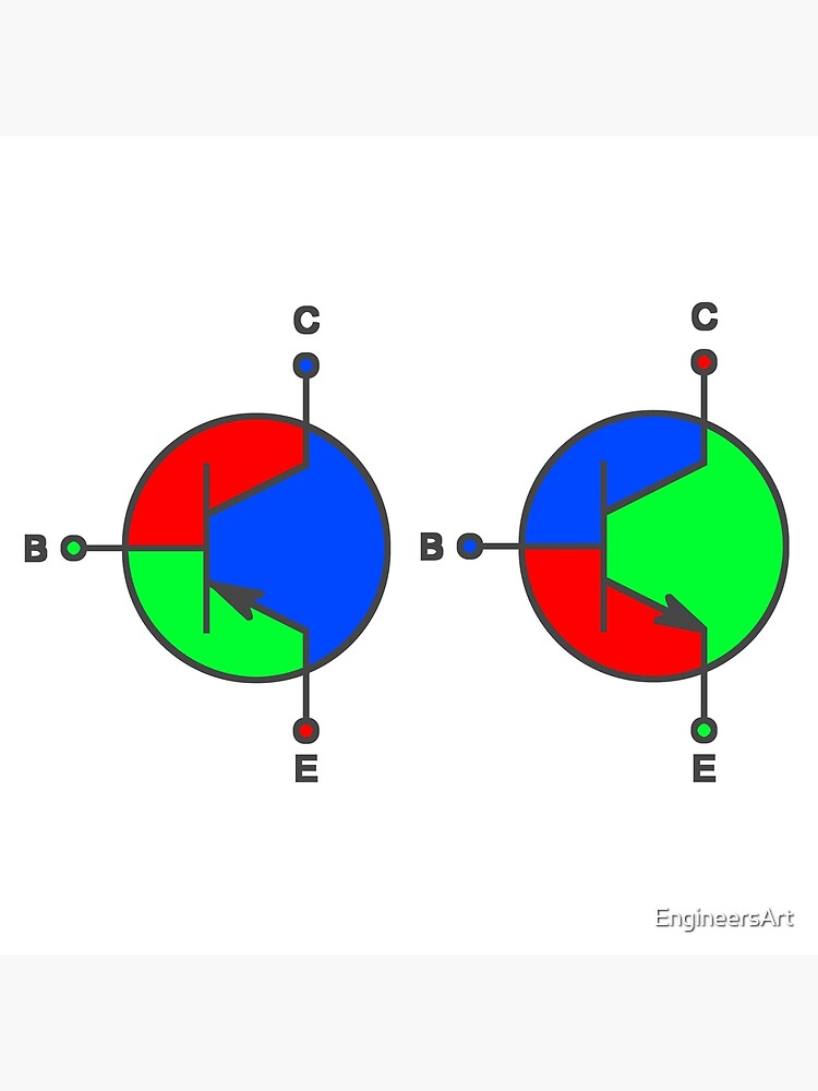
The transistor diagram illustrates the physical arrangement and connections of the emitter, base, and collector terminals. The arrow inside the emitter symbol represents the direction of conventional current flow. The base terminal controls the current flow between the emitter and collector, acting as a gate that allows or blocks the current
Useful Components Choccy Block Transistor Radio
Transistor Symbols: For the sake of convenience, the transistors are represented below by a schematic diagram. The symbols of NPN and PNP transistors are shown distinctly. Basic transistor symbol is shown without the arrow (inward and outgoing). The arrow symbol shows the flow of current within the transistor hence representing if it is a PNP
Source Image: quora.com
Download Image
The two transistors look nearly identical so we need to check the part number to tell which is which. With a NPN transistor, we have the main circuit and the control circuit. Both are connected to the positive of the battery. The main circuit is off, until we press the switch on the control circuit.
Source Image: redbubble.com
Download Image
Scheme of parallel connection post with transistor switch | Download Scientific Diagram May 22, 2022A block diagram is a graphical method of representing the relationships among variables in a system. The symbols used to form a block diagram were introduced in Section 2.2. … 1969. ) model for the transistor and is shown in Figure 2.7\(b\). Node equations are(G’s and R’s (or g’s and r’s) are used to identify corresponding conductances and

Source Image: pinterest.com
Download Image
Block Diagram Of Transistor
May 22, 2022A block diagram is a graphical method of representing the relationships among variables in a system. The symbols used to form a block diagram were introduced in Section 2.2. … 1969. ) model for the transistor and is shown in Figure 2.7\(b\). Node equations are(G’s and R’s (or g’s and r’s) are used to identify corresponding conductances and The transistor is the main building block “element” of electronics. It is a semiconductor device and it comes in two general types: the Bipolar Junction Transistor (BJT) and the Field Effect Transistor (FET). Here we will describe the system characteristics of the BJT configuration and explore its use in fundamental signal shaping and
43 Transistor ideas | transistors, electronics circuit, electronics projects
In reverse biasing we switch the terminals of the battery. The terminal to which p and n terminal attached plays a key role in deciding flow of current. There is will be flow of current in both cases but less (micro amperes) in Reverse biased PN junction compared to Forward biased ( in milliampere). Comment. Premium Photo | Details of an electronic device with electronic diagram electrical circuit transistors capacitor

Source Image: freepik.com
Download Image
Pin on Electrical & Electronics Concepts In reverse biasing we switch the terminals of the battery. The terminal to which p and n terminal attached plays a key role in deciding flow of current. There is will be flow of current in both cases but less (micro amperes) in Reverse biased PN junction compared to Forward biased ( in milliampere). Comment.

Source Image: pinterest.com
Download Image
Useful Components Choccy Block Transistor Radio The transistor diagram illustrates the physical arrangement and connections of the emitter, base, and collector terminals. The arrow inside the emitter symbol represents the direction of conventional current flow. The base terminal controls the current flow between the emitter and collector, acting as a gate that allows or blocks the current

Source Image: usefulcomponents.com
Download Image
Scheme of parallel connection post with transistor switch | Download Scientific Diagram The two transistors look nearly identical so we need to check the part number to tell which is which. With a NPN transistor, we have the main circuit and the control circuit. Both are connected to the positive of the battery. The main circuit is off, until we press the switch on the control circuit.

Source Image: researchgate.net
Download Image
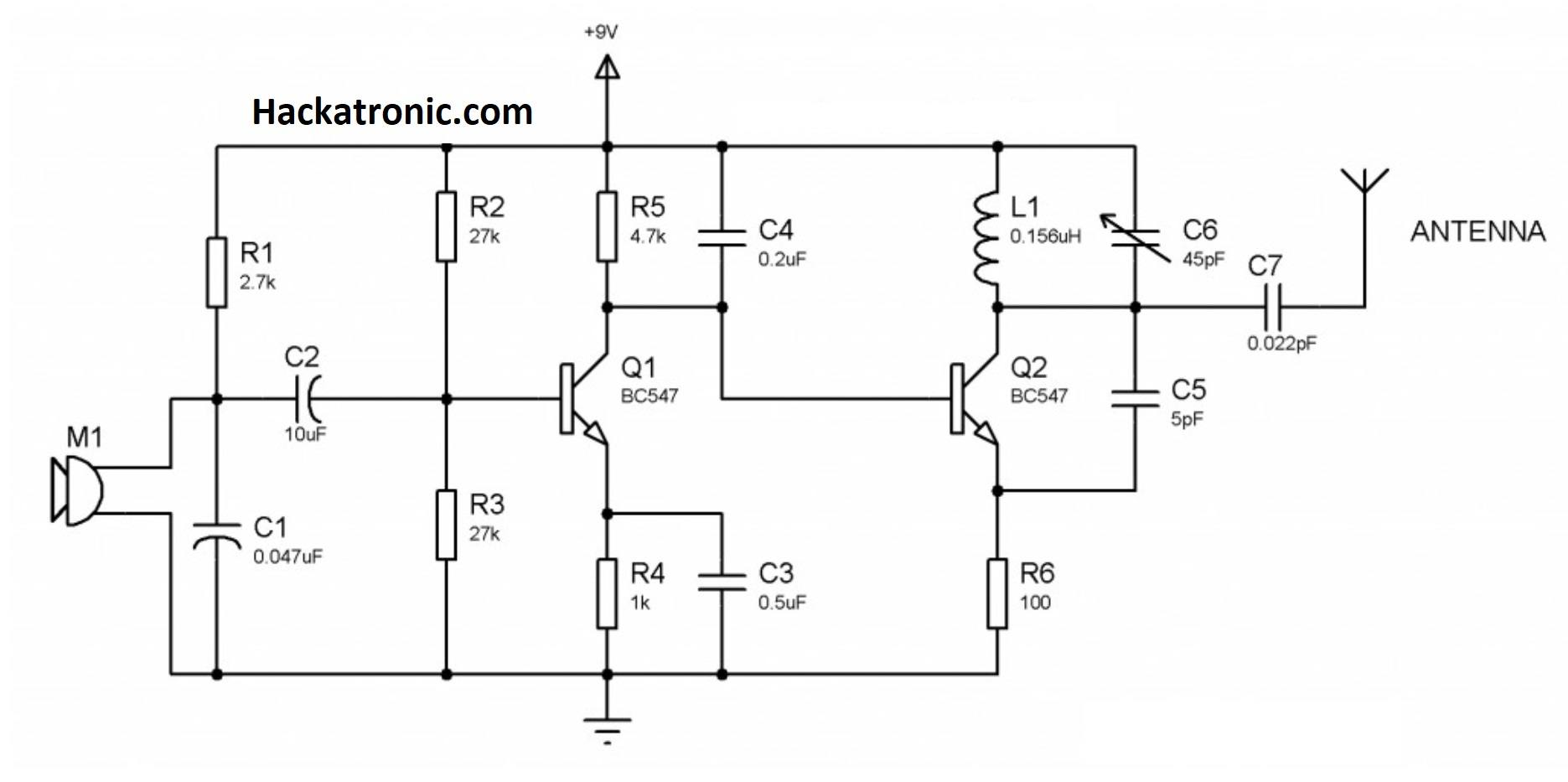
2,713 Transistor Diagram Images, Stock Photos, 3D objects, & Vectors | Shutterstock Block Diagram of FM Transmitter Working of FM Transmitter Circuit. The following circuit diagram shows the FM transmitter circuit and the required electrical and electronic components for this circuit is the power supply of 9V, resistor, capacitor, trimmer capacitor, inductor, mic, transmitter, and antenna. Let us consider the microphone to understand the sound signals and inside the mic

Source Image: shutterstock.com
Download Image
1 – 200 Transistor Circuits | Electronics circuit, Electronic circuit projects, Electronic schematics May 22, 2022A block diagram is a graphical method of representing the relationships among variables in a system. The symbols used to form a block diagram were introduced in Section 2.2. … 1969. ) model for the transistor and is shown in Figure 2.7\(b\). Node equations are(G’s and R’s (or g’s and r’s) are used to identify corresponding conductances and

Source Image: br.pinterest.com
Download Image
Bc 547 transistor projects » Hackatronic The transistor is the main building block “element” of electronics. It is a semiconductor device and it comes in two general types: the Bipolar Junction Transistor (BJT) and the Field Effect Transistor (FET). Here we will describe the system characteristics of the BJT configuration and explore its use in fundamental signal shaping and
Source Image: hackatronic.com
Download Image
Pin on Electrical & Electronics Concepts
Bc 547 transistor projects » Hackatronic Transistor Symbols: For the sake of convenience, the transistors are represented below by a schematic diagram. The symbols of NPN and PNP transistors are shown distinctly. Basic transistor symbol is shown without the arrow (inward and outgoing). The arrow symbol shows the flow of current within the transistor hence representing if it is a PNP
Scheme of parallel connection post with transistor switch | Download Scientific Diagram 1 – 200 Transistor Circuits | Electronics circuit, Electronic circuit projects, Electronic schematics Block Diagram of FM Transmitter Working of FM Transmitter Circuit. The following circuit diagram shows the FM transmitter circuit and the required electrical and electronic components for this circuit is the power supply of 9V, resistor, capacitor, trimmer capacitor, inductor, mic, transmitter, and antenna. Let us consider the microphone to understand the sound signals and inside the mic